What is PLC?
A Programmable logic controller (PLC) is a digital computer for the automation of electromechanical processes, Such as control of machinery on the factory assembly line, control of amusement rides, or control of lights.
PLCs are the most widely used electronic devices in the control of production and assembly process excess in most automated factories due to their simplicity and versatility.
A Programmable logic controller is a user-friendly, Microprocessor based, specialized computer carrying out control functions of many types and levels of complexity in industrial applications.
If you don't interest to read, watch the below video.
Why PLC?
- To reduce human efforts
- To get maximum efficiency from machines and control them with human logic.
- To reduce the complex circuitry of the entire system
- To eliminate the high cost associated with inflexibility, relay, and control system.
How is it Work
1. CPU: - it is the unit containing the microprocessor.
2. Power system unit: - is needed to convert the main AC voltage to low dc voltage
3. Memory unit: - is where the program is stored that is to be used for control action
4. Programming device is used to entered the required program into the memory of the processor
5. Input and output are where the processor receives information from the external devices and communicates information to external devices.
Advantages of PLC
- Increase the flexibility.
- Faster implementation of changes and corrections.
- Lower cost.
- Easy visualization of process running. increased reliability and maintainability.
- Increased security.
- Reprogramming capability.
- Elimination of wiring.
Programming languages of PLC
Ladder diagram
Functional block diagram
Structured text
Instruction list
Sequential flowchart
The program of logic controller hardware has two main categories as follows
Compact PLC:- fixed PLC or small type of PLC
Modular PLC:- Rack-mounted PLC or medium PLC
Types of PLC inputs
Digital input
- Level switches
- limit switches
- proximity sensor
- push buttons
- selector switches
Analog inputs
- Level
- temperature
- pressure
- flow
- speed
- weight
- position
Basic elements of ladder diagram
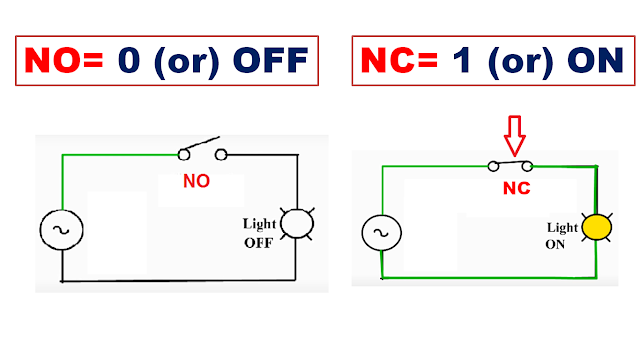
Working on NO & NC Switches
Normally open Switch (NO): - in Switches there are two contacts so, in this case, the two contacts were opened when will this type of switch be use if the load will be OFF. Show the above figure.
Normally Closed Switch (NC): - in Switches, there are two contacts so, in this case, the two contacts were closed when will this type of switch be used if the load will be ON. Show the above figure.
PLC Programming Layout
The Lift & Right sideline are Power lines called Rails. & Horizontal lines are called Rungs.
Programming Conditions

.png)


.png)
.png)
.png)
.png)
.png)
.png)